If you are a curious person, for a long time you may have been wondering the purpose of the following function, always called in myInit:
ortho 0.0 1.0 0.0 1.0 (-1.0) 1.0
The only thing you know about it is that it is related to how we are going to "view" the objects in our HOpenGL world, as I told you in Your First (and Simple) Program lesson.
This is exactly the topic of this lesson: viewing. Let's starting talking about projection.
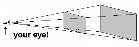
The Projection Matrix determines how objects are projected onto the screen, as its name suggests. It defines a viewing volume, and objects outside this volume are clipped so that they're not drawn in the final scene. "But what is a viewing volume?", you may ask. The answer is in the following picture:

HOpenGL tries to imitate the human eye. The viewing volume (the region you effectively see), in this case, corresponds to all of the volume (inside the pyramid) between the two gray planes. Although (part of) a primitive or a 3D object you drew may lie outside of the viewing volume, HOpenGL will display into the screen only what's inside of it. That's why you should define your viewing volume (in other words, the world's projection) correctly.
Keep in mind that the viewing volume must not necessarily be a pyramidal one. It can be a rectangular parallelepiped, or more informally, a box (the differences will be explained). To choose and set the type of your viewing volume, you first need to change the current matrix to the Projection Matrix and them initialize it (make it equal to the identity matrix). This is done by the following code:
	matrixmode Projection
	loadIdentity
Now you are ready to define the viewing rules of your world. You may choose between two of them: one type is the perspective projection, which matches how you see things in daily life. Perspective makes objects that are farther away appear smaller; for example, it makes railroad tracks appear to converge in the distance. If you're trying to make realistic pictures, you'll want to choose perspective projection.
The other type of projection is orthographic, which maps objects directly onto the screen without affecting their relative size. Orthographic projection is used in architectural and computer-aided design applications where the final image needs to reflect the measurements of objects rather than how they might look. Architects create perspective drawings to show how particular buildings or interior spaces look when viewed from various vantage points; the need for orthographic projection arises when blueprint plans or elevations are generated, which are used in the construction of buildings. [These two last paragraphs were taken from the OpenGL Programming Guide (The Red Book).]
The perspective projection corresponds to the pyramidal viewing volume, while the orthographic projection corresponds to the "box" volume. If you'd like to use the perspective projection, then you should use function frustum (after changing the current matrix to the projection one and initializing it, of course). Here you have the signature of this function:
frustum :: GLdouble -> GLdouble -> GLdouble -> GLdouble -> GLdouble -> GLdouble -> IO ()
The usage of this function is:
frustum :: left right botton top near far
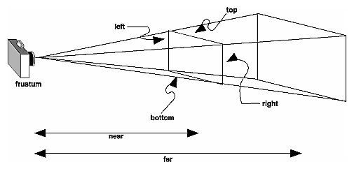
The following picture [also taken from the OpenGL Programming Guide (The Red Book)] may make it easier to understand:

The first four parameters describe the size of the near clipping plane, while the two last parameters give the distances from the viewpoint to the near and far clipping planes. Notice that all of them needs to be positive.
If you find frustum not very intuitive to use, you may try to use function perspective, from the Utility Library (GLU). Here you have its signature:
perspective :: GLdouble -> GLdouble -> GLdouble -> GLdouble -> IO ()
And its usage:
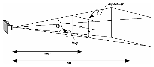
perspective :: (field of view) aspect near far
Here, the field of view (or just fov) is the angle of the field of view in the x-z plane, in degrees. It must range from 0.0 to 180.0. The aspect is the aspect ratio of the frustum: its width divided by its height. For a square portion of the screen, the aspect ratio is 1.0. Finally, near and far are still the same, and again they must be positive. Check out the following picture [you already know from where it was taken]:

If you wish to use a orthographic projection, in which the distance from the viewpoint doesn't affect how large an object appears, you'll have to use the function ortho (now you finally know its use!):
ortho :: GLdouble -> GLdouble -> GLdouble -> GLdouble -> GLdouble -> GLdouble -> IO ()
Its usage is:
ortho left right bottom top near far
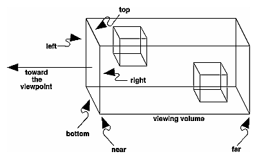
The difference here is that near and far can be negative, the direction of projection is always parallel to the z-axis, and the viewpoint faces toward the negative z-axis (into the screen). The following picture says everything about ortho [including from where it was taken]:

We have been using an orthographic projection so far because our examples until now were all bi-dimensional (2D).If you are going to make a program in which you are sure that you'll always work with two-dimensional images onto a two-dimensional screen, you can also use another Utility Library (GLU) routine, called ortho2D:
ortho2D :: GLdouble -> GLdouble -> GLdouble -> GLdouble -> IO ()
Its usage is:
ortho2D left right bottom top
The difference from ortho and ortho2D is that all the z coordinates for objects in the scene are assumed to lie between ortho2D. In other words, if you always use Vertex2 rather than Vertex3 to declarate the vertices of your primitives, you'll never get objects clipped (not shown) because of their z values.
The frustum and ortho functions are defined in module GL_CoordTrans, which is automatically imported if your program already imports module GL, while perspective and ortho2D are defined in module GLU_Matrix, which is automatically imported if your program already imports module GLU.
Now I'm going to introduce you to a new type of callback procedure: the reshapeFunc. Every time your program window is reshaped, the function declared by reshapeFunc is called. The interesting thing about this is that this function will automatically receive the new width and height of the window.
Translating this to code, suppose a function called reshape will be your reshapeFunc callback procedure. Declare it in the main:
reshapeFunc (Just reshape)
Its signature must be:
reshape :: ReshapeAction
Where a ReshapeAction is defined as follows:
type ReshapeAction = WindowSize -> IO ()
All of this stuff is defined in module GLUT_CBWindow, which is automatically imported if your program already imports module GLUT.
Now you may ask what is the relation between a reshape callback with viewing. The answer is simple: viewport.
What is a viewport? The answer is simple: the viewport is the rectangular region of the window where the image is drawn. To set this, call function viewport:
viewport :: WindowPosition -> WindowSize -> IO ()
The WindowPosition parameter specifies the lower-left corner of the viewport, and the WindowSize parameter specifies the width and height of the viewport (the size of the viewport rectangle).
Suppose now that you defined your viewport and then the window is reshaped. The new window may not correspond to the old viewport. For example, if you use the whole window as the viewport, two things can happen when the window is reshaped:
That's why the best place to call viewport is in the reshape callback procedure (because you have the current size of the window). Observe the following code:
	reshape :: ReshapeAction
	reshape screenSize@(WindowSize w h) = do
   		viewport (WindowPosition 0 0) screenSize
   		...
This sets the viewport to the whole window. The @ here says that every time this function refers to screenSize, actually it is referring to (WindowSize w h). The following code, without the @, has the same effect, but is less elegant:
	reshape :: ReshapeAction
	reshape (WindowSize w h) = do
   		viewport (WindowPosition 0 0) (WindowSize w h)
   		...
The viewport function is defined in module GL_CoordTrans, which is automatically imported if your program already imports module GL.
		reshape :: ReshapeAction
		reshape screenSize@(WindowSize w h) = do
   			viewport (WindowPosition 0 0) screenSize
   			matrixMode Projection
   			loadIdentity
   			let	near   = 1
				far    = 80
				fov    = 90
				ang    = (fov*pi)/(360 :: Double)
				top    = near / ( cos(ang) / sin(ang) )
				aspect = fromIntegral(w)/fromIntegral(h)
				right = top*aspect
   			frustum (-right) right (-top) top near far
   			matrixMode Modelview
Modelview Matrix. This is a wise thing to be done, since we only need to use the Projection Matrix when setting the projection type. We'll talk more about the Modelview Matrix in the next lesson.loadIdentity before setting the projection! Weird things can happen otherwise...